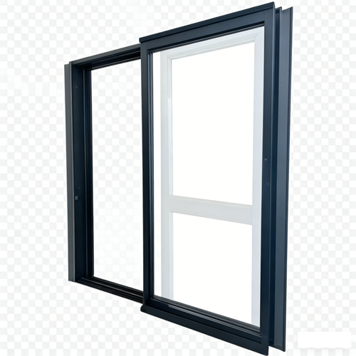

Read this before you copy any number out of this article
Every dimension below is either published in the ALPES TS130 specification or quoted from a publicly published source and labelled as such. The arithmetic is ours, and we show you the working. None of it is a project drawing. Do not paste any of it into a CAD file, a specification or an order without checking it against your own opening, your own wall build-up and your own authority having jurisdiction.
One more thing up front, because it shapes everything after it: the file you want and the file we manufacture from are not the same file. This article is mostly about the gap between them.
Type TS130 side press window CAD into a search box and you are usually asking for one of four different things, and the one you get back is rarely the one you needed. A two dimensional block to drop into a floor plan. A section detail for a head, a jamb and a sill. A three dimensional object for a model. Or the file a machining centre cuts from. They share a name and almost nothing else.
The side press window is where that confusion costs the most. The thing that makes it a side press window is a few millimetres of travel perpendicular to the plane of the glass, and that travel is the one thing none of those four files shows by default. A block can be dimensionally perfect in every number it does show, and still be a drawing of a different product.
Before arguing about what goes in the file, it helps to name which file we are talking about.
| File | Who uses it | What it is drawn for | What it cannot tell you |
|---|---|---|---|
| Plan and elevation block, usually DWG | The architect or drafter | Where the opening is, how many panels, and which tag goes on the schedule | Anything about depth into the wall, the threshold, or whether the sash presses or merely slides |
| Head, jamb and sill detail | Whoever details the wall | The junction with the wall build-up, the flashing, the drainage route and the reveal | Anything about the mechanism. A detail is a knife cut through one place; it shows what that cut passes through and nothing else |
| Model object, for a family or an exchange format | The coordinator, for clash detection and quantities | Whether it fits, and how many of them there are | Tolerances, travel, and where the hardware holes are drilled |
| Fabrication file, DXF or DWG at one to one with cut lengths and hole coordinates | Our machining centre | Cutting profiles and drilling the hardware holes | Anything about your wall. It describes our parts, not your opening |
We have written elsewhere about what a fabrication drawing is and is not, and about the three numbers that share one name. This piece starts where that one cannot reach: the file that leaves our office and lands inside yours, and what has to be in it before a side press window can be described on a drawing at all.
Start with the mechanism, because the whole argument follows from it. One published explanation of side pressure sliding windows describes it in two halves: when the handle is rotated, the sash first disengages from the frame through a lifting or shifting movement so that it can slide along the track; when the handle returns to the locked position, the sash is pulled back against the frame and the sealing gasket is compressed right around the sash. The same source puts that compression at approximately five to eight millimetres.
A Chinese language description of the same family splits the movement into named stages, which is useful because the names are the drawing. There is a translation stage, in which the sash slides along the track to the closed position and aligns with the fixed light. Then there is a side pressure stage, in which operating the handle drives the linkage and moves the sash perpendicular to the plane of the window by several millimetres, compressing the gasket evenly all the way round. Opening reverses the order: the sash first retreats out of the seal, and only then slides away.
So the sash has at least three conditions, not two. Pressed home and sealed. Released and free to slide. And parked anywhere along the track, which a published description of the family lists as a feature in its own right, because a sash that can be stopped at any position gives you a controllable ventilation gap instead of an all-or-nothing opening.
A CAD block is a picture of one condition. It is almost always the closed one, which is precisely the condition in which the mechanism is least visible. Now put that beside the scale at which window blocks are normally drawn. The left two columns below follow published guidance on window CAD blocks; the right column is our own arithmetic, applied to the five to eight millimetre range quoted above.
| Scale | What a window block normally carries | What five to eight millimetres of travel looks like on the sheet |
|---|---|---|
| 1:200 | The opening as a break in the wall, a single glazing line, no frame | 0.025 to 0.04 mm |
| 1:100 | Jamb lines, one glazing line, sill projection, a window tag | 0.05 to 0.08 mm |
| 1:50 | Frame and sash lines, reveal depth, opening marks in elevation | 0.1 to 0.16 mm |
| 1:20 | Separate frame and sash profiles, glazing thickness, sill fall | 0.25 to 0.4 mm |
| 1:5 | Head, jamb and sill details: full profile with seals, thermal break, flashing, fixings | 1.0 to 1.6 mm |
| 1:1 | The fabrication file | 5 to 8 mm, the first scale at which it can be drawn at all |
Read the right-hand column downwards. The movement that makes this window worth specifying is under a tenth of a millimetre at the scale most window blocks are drawn at, and it does not reach one whole millimetre until 1:5. Every block you have ever inserted into a general arrangement plan has omitted it, and every one of those blocks was, strictly speaking, correct.
There is a second way to see how big the number really is. Five to eight millimetres is between about a fifth and about a third of the 26 mm frame face you can see on the TS130 elevation. It is under one sixteenth of the 130 mm that goes into the wall. It is small enough to fall out of every view anyone draws, and large enough to be the entire reason this is not an ordinary sliding window.
The TS130 is published with five cross-section figures, and they are the only hard numbers any drawing of it can be built from. What matters for CAD is that they do not live in the same view. Every one of them is published on the ALPES sliding window range, and none of them appears in all three views.
| Published number | Where it appears in a CAD set | What it is | What it is not |
|---|---|---|---|
| Frame wall width, 130 mm | Horizontal section through the jamb, and the plan detail | The depth the system occupies in the wall | Not a width you can see, and not your wall thickness. It is one layer of a build-up, not the build-up |
| Glass sash thickness, 55 mm | Horizontal and vertical sections | The build-up depth of the moving panel that carries the glass | Not the glass thickness, and not the rebate the glass sits in. Those are two other measurements, and neither is in the catalogue |
| Sash width, 75 mm | Elevation | The visible vertical member of the moving panel | Not the interlock, and not the daylight opening. Both of those are separate numbers |
| Frame width, 26 mm | Elevation | The visible face of the fixed frame against the wall | Not the sightline. The sightline is the sum of the members, and no catalogue prints a sum |
| Track height, 53 / 31 mm | Vertical section at the sill, and nowhere else | The two threshold options | Not on the elevation and not on the plan block. If you have only ever seen the elevation, you have never chosen a threshold |
No single view carries all five. Two of them live only in a vertical or horizontal section. Two live only in an elevation. One lives only at the sill. So the practical answer to “send me the CAD” is a question: which of these five do you need, and are you prepared to receive the view that contains it?
Here is an arithmetic coincidence worth knowing before you read any section drawing. The TS130 frame wall width is 130 mm. Its glass sash thickness is 55 mm. Subtract one from the other and you get 75 mm.
The published sash width of the TS130 is also 75 mm.
Two completely unrelated measurements land on the same number. One is what is left over in depth once the sash build-up is taken out of the frame depth. The other is a visible width across the elevation. If a drawing shows you 75 with no view label and no dimension string, you cannot tell which one you are looking at, and the two are ninety degrees apart.
This is the clearest reason a single file cannot answer a CAD request. On a horizontal section, the 75 that is a leftover is measured along the same axis as the 130 and the 55, and the 75 that is a width is not on the drawing at all. On an elevation, it is the other way round. Send the wrong one and everything on it is still true.
Take a 2400 mm wide unit with the two panel layout, one fixed plus one movable. Everyone who has ever specified a window has done this sum. The interesting part is where it stops.
| Step | Running total | What is still missing |
|---|---|---|
| Start with the unit width | 2400 mm | Nothing yet. This is the number the schedule gives you |
| Take off two sash members, 75 mm each | 2250 mm | The frame faces, and the overlap where the two sashes meet |
| Take off two frame faces, 26 mm each | 2198 mm | The interlock overlap, which is not published anywhere we have seen, and the glass rebate |
| Split across two panes | About 1099 mm each | Whatever the interlock takes, which the block does not know |
So a block will tell you there are 2198 mm of glass in a 2400 mm unit, and that figure is the most that could be true. The overlap where the two sashes meet still comes off it, and that number is on the section or it is nowhere. A block cannot finish the sum, because the last term of the sum is a piece of interlock geometry that lives in a view the block does not have.
Now run the same arithmetic for the three panel layout, middle fixed with two moving sashes, on the same 2400 mm unit: 2400 − 26 − 26 − (4 × 75) = 2048 mm. The third panel costs exactly two sash widths of glass, 150 mm, before you have paid for anything else. That is the number to put in front of anyone who wants the symmetric three panel look: out of 2400 mm, the symmetry costs 150 mm of glass plus a second interlock, and it buys back a panel that can never move.
The TS130 is published with an eight point locking system. Counts are easy to put in a catalogue and impossible to put in a drawing, because a drawing has to say where they are.
That matters more here than on almost any other window, because on a side press window the lock points are not a security feature. They are the pressing mechanism, and the gasket only compresses evenly if all of them have the same travel. A published description of the family says exactly what goes wrong when they fall out of step: if the sash has drifted, the travel at each pressing point is no longer the same, some points reach full compression and others are short by a few millimetres, and the gasket is no longer compressed evenly. The published remedy is not a new gasket. It is to re-align the sash and check that the lock points along the transmission rod are still synchronised.
Two consequences follow for the file. First, eight points are eight coordinates at specific heights, not eight identical symbols, and those coordinates are a function of sash height. One block reused across three different sash heights is three drawings, two of them wrong. Second, the drawing is the only place where the count becomes positions, and the positions are the only thing anyone can check on site. A catalogue that says eight tells you nothing you can verify, and a drawing that says eight without coordinates tells you barely more.
| What the hardware has to say on the drawing | Why an ordinary slider does not need it | What happens if it is left off |
|---|---|---|
| The number of pressing points | A plain slider presses nothing; it has a latch | Nobody knows how many places have to be adjusted after the first season |
| The height of each point, from one stated datum | One latch sits in one place | A block reused across sash heights quietly relocates the mechanism |
| The direction and amount of travel at each point | A slider stays in its plane for its whole life | Uneven compression gets diagnosed as a failed gasket, and the gasket gets replaced for nothing |
| Which way the handle turns, and through what angle | A slider handle does almost nothing | The handle envelope collides with the blind or the curtain, which are not on your drawing either |
| What has to be re-synchronised after the sash is re-aligned | There is nothing to synchronise | A five minute adjustment becomes a call-out and a parts order |
A published patent for a sliding sash translation and side pushing structure describes the moving parts with the gaps left in, which is unusual and useful. The translation pulley seat is deliberately left with a clearance so that it can slide sideways inside its fixed seat, and with a clearance in elevation so that it can swing up and down about its axis to absorb the height and undulation changes of the track. The side push itself runs along a bent guide groove with a straight section, a connecting section, and a second straight section, and the pulley shaft travels from one straight section to the other.
So the assembly is not rigid, and it is not meant to be. Those gaps are design. That creates a drawing problem with two failure modes. If the section shows the parts touching, the installer reads the play as slop and shims it out, and the mechanism then fights itself. If the section shows the gaps but does not dimension them, nobody can tell how much movement is acceptable and how much is wear. The drawing has to declare the clearance as a clearance, with a number, in the same view as the travel.
Worth noting how the mechanism is made, too, because it explains why a drawing is not optional here. One published description of side pressure hardware says the holes for the transmission boxes and the lock keeps need high positional accuracy and should be prepared on CNC machining centres, with the frames and sashes cut at 45 or 90 degrees and the diagonals checked for square. None of that can be improvised from an elevation block. It all comes from coordinates in a file.
The TS130 is published with two track heights, 53 mm and 31 mm. Subtract one from the other and you get 22 mm.
Now compare that with the 26 mm visible frame face on the elevation. The choice between the two track options moves your threshold by almost as much as the frame you will be looking at for the life of the window, and it is a choice that appears in exactly one view: the vertical section at the sill.
And once it is on that section, it has to agree with the finished floor level, which is usually drawn by whoever is doing the floor, not by whoever is doing the window. Track height is the cleanest example of a general rule: the numbers that decide whether a window is pleasant to live with are almost never in the view most people ask for.
Published guidance on window CAD blocks is unusually blunt about what goes wrong. The faults named most often are these: the wall left unbroken behind the block, so the wall line runs straight through the glass; blocks exploded, which breaks the link to the schedule and the tag; opening marks left off the elevation, which hides a fixed light from an opening one; text placed inside a block, which mirrors into reversed and unreadable tags; and one geometry used at every scale.
Set against that list, these are the habits worth insisting on before you accept any window file, including ours.
And one habit that is specific to this product. The elevation mark has to say which panel moves and how it moves. The published fault list warns that leaving opening marks off the elevation hides a fixed light from a casement. On a side press window it hides something worse: it hides the fact that the moving panel both slides and presses, which is the only reason to specify it over a cheaper slider.
| What has to be added | Why a plain slider’s set does not have it | Where it has to appear |
|---|---|---|
| The travel, roughly five to eight millimetres, dimensioned | A plain slider never leaves its plane | Horizontal section, both states, dimensioned from one datum |
| Two conditions of the same sash | A plain slider has one position per place on the track | Two overlaid outlines on the section, or two sheets |
| Pressing point coordinates | A plain slider has one latch in one place | Elevation of the sash, dimensioned from one datum, per sash height |
| The handle’s operating envelope | A plain slider’s handle does almost nothing; a published 130 series from another maker describes a transmission box driven by a handle operating through 180 degrees | Plan, on the room side, checked against blinds, curtains and the mesh |
| The park-anywhere condition | A plain slider parks too, but nobody specifies it, because it is not sealed when it does | A note, not a drawing. One note prevents the most common complaint about this family |
| The second sash, if you specify the inward opening mesh, and its own swing arc | A plain slider’s mesh slides, so it costs no floor area | Plan, on the room side. This is the arc that lands on the sofa |
Three things, briefly, because they are the ones people expect a CAD file to answer and it cannot.
Most weeks we also get file requests for product families we do not build. If your search was really about wood bi fold closet doors, or a 32 folding door, or a 42 entry door, we would rather tell you that our catalogue pages for those are empty than send you a window file with a different name on it.
What we can still do is tell you what those drawings have to contain, because the discipline is identical even though the file is different. A folding door drawing has to dimension the stack of parked panels, not the opening, and the stack is what eats the wall. A swing door drawing has to fix the handing and draw the arc. An entry door drawing has to fix the threshold and the handing, and the threshold is a level that somebody else’s floor has to meet. In every case the rule is the same one that governs the TS130: the drawing is where a mechanism becomes coordinates, and a mechanism that never becomes coordinates gets decided on site, by whoever arrives last.
| Item | Status | Why there is a gap |
|---|---|---|
| The five cross-section numbers: 130, 55, 75, 26, and 53 or 31 | Published | They are system dimensions measured on a section. None of them is measured on your opening |
| The 200 kg pulley rating | Published | It is a rating per sash, and it is not a maximum sash size. The two get confused constantly |
| Eight point locking, and the hardware brand | Published | The count is published. The coordinates are per unit, and only a drawing carries them |
| The side pressure travel | Published by others as a range, roughly five to eight millimetres; ours to be confirmed for your sash | A published range describes a mechanism family. It is not our tolerance for your unit |
| The glass rebate | Not published | The 55 mm is the sash build-up. What the glass actually sits in is a different measurement, on the section |
| The interlock overlap | Not published | It is the last term of the daylight sum, and it is on the section or nowhere |
| Maximum sash size | Not published as a single figure | It is a function of your glass and your wind load. Any single number would be a guess |
| A thermal value for this series | Not published | Ask for a calculated value for your size and your glass configuration, under a named standard |
| The drainage path | On the section | It is a route with outlets, not a number. Nobody can infer it from an elevation |
This is the block we would want pasted into an email. The third column is the one worth reading.
| Line | What to write | If it is left blank |
|---|---|---|
| 1 | Unit width and height in millimetres, as a manufacturing size | You get a drawing of a window that is not the one you have an opening for |
| 2 | Which number that is: nominal, frame, or structural opening | Everyone is right and nothing fits |
| 3 | Panel layout: one fixed plus one movable, or middle fixed with two movable | The daylight sum changes by 150 mm and the drawing does not mention it |
| 4 | Track height: 53 mm or 31 mm | Somebody picks a threshold for you, and the tiler finds out on site |
| 5 | The wall build-up, layer by layer, outside to inside | We assume a wall, and it will not be yours |
| 6 | The frame depth you can accept | 130 mm is assumed, and may not meet your insulation line |
| 7 | Glass specification, with thickness | The rebate cannot be confirmed, and the rating has nothing to be checked against |
| 8 | Sash height, per sash, not per unit | The pressing point coordinates cannot be set, and the block lies about them |
| 9 | Handle side, and the clearance you have on the room side | The handle lands exactly where the blind is |
| 10 | Mesh: none, or the inward opening sash | A second sash with its own arc is discovered on site |
| 11 | The format you can actually use: DWG to insert, DXF at one to one to machine, PDF to read | You get a PDF and cannot measure it, or a DXF and cannot read it |
| 12 | Units and scale stated in the file, and a revision number on the sheet | Millimetres land in an inch drawing, and the second revision gets built from the first |
| Question | The answer you want | The answer that sounds like one and is not |
|---|---|---|
| Can I have the CAD block? | A dimensioned section plus an elevation with opening marks | Here is the DWG. One view, no travel dimensioned |
| Is the block the real size? | Yes, drawn one to one in millimetres, with the unit written in the file | It is to scale |
| What is the sightline? | The sum of the members, measured on your section | 26 mm. That is the frame face, not what you see |
| How thick can the glass be? | The rebate, dimensioned on the section | 55 mm. That is the sash build-up |
| How much does it open? | The travel, the parked positions, and the net clear opening, as three separate numbers | It opens fully |
| Will one drawing work at any scale? | No. Ask for the scale band you draw at, and expect two or three versions | It is a block, it scales |
| Can I reuse it across the project? | Only where the sash height is identical, because the pressing point coordinates move with it | One block covers the family |
| Is 200 kg the limit on glass? | No. It is a rating per sash. Ask for the maximum size for your glass | Any glass up to 200 kg |
| Can I change the glass after approval? | Not without re-issuing, because the size and the rating move together | Yes, it is the same frame |
| Does the file show the drainage? | It must, as a route with outlets you can point at | It is in the profile |
What we would rather send is two things rather than one: an elevation with the opening marks on it, and a horizontal and vertical section with the numbers dimensioned. A single downloadable block is the deliverable people ask for and the one that cannot carry this product, because the movement that defines it is invisible at the scale a block is drawn at.
Because it has two conditions. Released from the frame and free to slide, and pressed home against the gasket. Published descriptions of the family describe exactly this sequence: the sash must first be released, and only then can it translate; closing reverses it. A section that shows one condition is a section of half a window.
You can, and that is the problem. Scaling a block that was drawn for one scale band into another is the fault that published guidance names most often: it is either a black blob or an empty outline, and in both cases the travel has quietly gone. Ask for the version drawn for the scale you work at.
Two, at least. One at the scale of your general arrangement, usually 1:100 or 1:50, for the plan and the elevation. And one at 1:5 or 1:2 for the head, jamb and sill, where the seals, the thermal break and the fixings live. Published guidance on window blocks suggests holding two or three versions of each window for exactly this reason.
Because the two are different measurements and both are usually called the size. The 130 mm is a depth into the wall, not a width across it. Your opening is a hole in a wall; the frame is a thing that goes into it, and the gap between them is somebody’s decision, not a constant. Send us the wall build-up and we can tell you what the frame should be.
Only where the sash height is the same. The pressing points are positioned along the sash, so their coordinates are a function of its height; a single block applied across three heights puts the mechanism in the wrong place on two of them. If your elevations have more than one window height, you need more than one drawing.
Before you send the file request
Nothing in this article is a drawing, and nothing in it should be pasted into one. The five to eight millimetre travel is a range published by a third party for a mechanism family, not a tolerance we are stating for your unit. The arithmetic is ours and is shown so that you can check it, not so that you can copy it.
Send us the twelve lines in the table above, in millimetres, with your wall build-up and your glass, and we will return sections and an elevation that carry your numbers rather than ours.
And one last thing, because it is the most useful sentence here: a drawing is where a mechanism becomes coordinates. Anything that never becomes coordinates gets decided on site, by whoever arrives last.