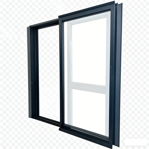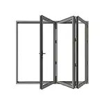

Ask for ALPES sliding window dimensions and you will be handed a list of true numbers. The TS130 side-press window in our sliding-window catalogue publishes a 130 mm frame wall width, a 55 mm glass sash thickness, a 75 mm sash width, a 26 mm frame width and a 53/31 mm track height. Every one of them is accurate. Not one of them is a size you can order a window in.
Those numbers describe a cross-section. They tell you how deep the frame sits in the wall, how much material stacks up at the sash, how wide the visible line is, and how tall two different rails are. They do not tell you what to write on a purchase order, and they certainly do not tell you what the hole in the wall has to be. A specification line that only carries a phrase like tcp sliding window carries no size at all. It carries a product family, and a product family is not a dimension.
This is not an ALPES problem, and it is not a Chinese-manufacturer problem. It is arithmetic, and it is identical everywhere. What separates a project that fits from a project that fights is not who had the better size chart. It is who decided, in writing, how much each party was allowed to be wrong.
A window's nominal size is usually settled in an afternoon. What consumes the rest of the project is the tolerance: whose millimetre it is, what it is measured against, at what temperature, and who pays when two perfectly honest tolerances add up to an assembly that does not close. We have written elsewhere about how to read one series' published dimensions and what each of them means. This piece starts where that one stops.
Do not copy thresholds out of this article, including this one. Every number quoted here is a publicly published figure from a named standard, a named technical source, or a named supplier's guidance, and each of them belongs to a specific scope, edition and measurement condition. Confirm the edition that applies to your project, and put the values you actually intend to enforce into your own contract documents.
Before you argue about a size, it helps to see who is allowed to be wrong and by how much. The table below collects published tolerances and published gap figures from five different places in the chain. None of these numbers was invented for this article; each is the kind of figure a specifier can go and look up.
| Stage | Who decides it | Publicly published magnitude | Who pays when it is exceeded |
|---|---|---|---|
| Structural opening, masonry or concrete | The builder, on site | Published acceptance records for masonry give opening width and height at plus or minus 10 mm, with window position offset up to 20 mm; some project technical documents work to plus or minus 5 mm or to an asymmetric band | Main contractor, before the window arrives |
| Structural opening, precast panel | The precast producer, in the factory | One published technical summary puts precast openings within plus or minus 3 mm with a diagonal difference not exceeding 5 mm | Precast supplier, and it is the tightest link in the chain |
| Coordinating size and construction size | The designer, on the drawing | The Chinese opening series standard defines a nominal coordinating size and a separate construction size, and states that the construction size may be larger than, equal to, or smaller than the nominal size depending on the fixing method | Design team, usually discovered during shop drawing review |
| Window fabrication | The factory, at the saw and the assembly bench | The aluminium windows and doors product standard gives construction width and height tolerances of plus or minus 1.5 mm up to 2000 mm, plus or minus 2.0 mm from 2000 to 3500 mm, and plus or minus 2.5 mm above 3500 mm, with a diagonal difference limit and a frame-to-sash overlap tolerance for windows of plus or minus 1.0 mm | Manufacturer, and it is the smallest number in the chain |
| Temperature | Nobody. Physics. | A 6060-series aluminium profile with a coefficient near 23.4 parts per million per kelvin moves roughly 3.5 mm over three metres across a 50 kelvin swing | Whoever fixed the frame so it could not move |
| Installation gap and finish build-up | The site, and whoever chose the cladding | Published guidance ranges from about 10 mm per side on a bare wall or sub-frame, through 15 to 20 mm for cement render, 20 to 25 mm behind tile, and 40 to 50 mm behind stone on a support system | Installer, and the gap is the largest number in the chain |
Read that table top to bottom and one thing jumps out: the wall is allowed to be wrong by roughly four to six times as much as the window is, and the gap left around the window is allowed to be roughly ten to twenty times as much as the window's own tolerance. The factory holds the tightest number in the entire chain. It is also the party everybody blames first.
Here is the comparison that reframes most dimensional disputes.
A window fabrication standard permits a construction size error of about 1.5 to 2.5 mm depending on how big the unit is. That is the number the factory is measured against. A three-metre aluminium frame, sitting in the sun, moves by roughly 3.5 mm on its own across a fifty-degree swing in service temperature, because that is what a coefficient near 23.4 parts per million per kelvin does to three metres of metal.
So the amount the factory is allowed to be wrong by is smaller than the amount the weather moves the product by, before anybody installs anything.
That statement is not a defence of sloppy fabrication. It is the reason a window can arrive fully compliant and still not fit, and it explains a whole family of site arguments. The frame that was measured on a cool morning and fixed rigidly will spend its first summer looking for the room it was not given. The sash that binds at two in the afternoon and runs freely at eight in the morning is very often reporting a movement problem, and replacing the hardware to fix a movement problem is the most expensive possible answer to it.
There is a reason this feels counter-intuitive: dimensional tolerances are specified at a reference temperature. The international standard that fixes it sets the standard reference temperature at 20 degrees Celsius, and it has been 20 degrees since the original recommendation in the early 1950s. The most recent edition clarifies that the value is 20 degrees on the international temperature scale. The national metrology institute that led that revision puts the underlying point plainly: a dimensional or geometric tolerance on a drawing has no meaning unless the temperature it holds at has also been agreed.
In other words, the 1.5 mm in the standard is a number at 20 degrees. Your wall is not at 20 degrees, and neither is the container the window crossed the equator in, and neither is a dark frame on a west elevation at three in the afternoon.
Published expansion data makes the differential easy to see. Over the same three metres and the same fifty-degree swing, a carbon steel element moves about 1.8 mm, a 304 stainless element about 2.6 mm, float glass about 1.35 mm, and the aluminium frame about 3.5 mm. The glass in the middle of the frame moves at roughly a third of the rate of the metal holding it.
Three practical consequences follow, and none of them is a product claim:
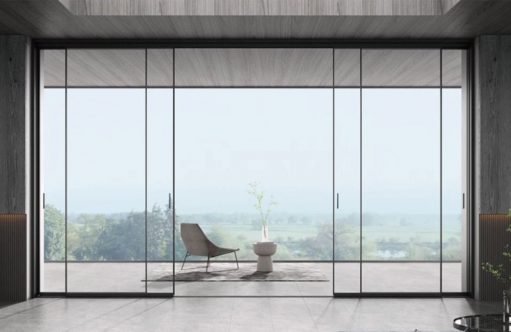
If your project is a fully glazed room rather than a single window, this section is the one to redo with your own numbers. A glass enclosure sees the widest service temperature range of any element on the building, which is why a specification that starts as a portable sun room needs its movement allowance written down before the sections are cut, not after.
Most people treat the installation gap as a constant, something like "leave fifteen millimetres". It is not a constant. It is a function of what is going on the wall afterwards.
The Chinese opening-series standard separates the nominal coordinating size from the construction size and then defines the installation gap as a set of sub-dimensions. It gives two installation methods: a dry method with a pre-set metal sub-frame, where the joint is at least 15 mm, and a wet method where the frame is set directly into the opening and caulked, where the joint is 10 to 20 mm. It also says explicitly that the thickness of the decorative layer has to be counted inside the total joint.
It also quietly destroys the most common mental model in the industry. The standard states that the construction size can be greater than, equal to, or smaller than the nominal coordinating size. The sign is not fixed. So the folk rule of "take the drawing size and subtract a gap" is not merely imprecise; the direction of the correction can be wrong, depending on where the positioning line sits and which fixing method is used.
| Finish condition | Reserve gap per side, published guidance | What it has to swallow | What happens if it was not reserved |
|---|---|---|---|
| Bare wall, or sub-frame installation | About 10 mm | Shimming, fixing and sealant only | No room to plumb the frame; gaps end up as sealant thickness instead of structure |
| Cement render | About 15 to 20 mm | The render layer thickness itself | The render licks over the frame edge and the joint becomes a crack with a bead on it |
| External tile | About 20 to 25 mm | Tile plus adhesive bed | Tiles are cut to chase the frame, and every cut is a permanent witness to the error |
| Stone on a support system | About 40 to 50 mm | Stone plus the depth of the support grid | The window is buried in the reveal and the drainage path disappears behind the cladding |
| External insulation system | Has to be calculated, not looked up | Insulation thickness plus finish thickness plus the fixing position | The frame ends up in the wrong plane relative to the insulation line, and the thermal bridge moves to the window |
From 10 mm to 50 mm is a factor of five, driven entirely by a cladding choice that may not have been made when the window was priced. Against a fabrication tolerance of 1.5 to 2.5 mm, that is a difference of an order of magnitude. This is why the question "what gap do you need" cannot be answered by a window supplier alone, and why the honest answer is a question back: what is going on the wall, and how thick is it.
One of the most common and most avoidable dimensional mistakes is subtracting the clearance twice.
A North American replacement-window guide states the industry convention plainly: the manufacturer takes the deduction, not you. You supply the smallest measured width and height, rounded down to the nearest eighth of an inch, and the maker builds the unit about a quarter of an inch smaller to the nearest eighth. If you deduct the quarter inch yourself as well, the unit arrives half an inch small and the joint is too wide to seal properly. Send the raw measured figure and say on the order that it is raw and undeducted.
The same logic applies in millimetres and in any market: one party owns the deduction, and it has to be written down which one. Two people each being helpfully conservative is not double safety. It is a gap nobody can seal.
And one red flag worth repeating from a fabricator's own measuring guide: if a supplier tells you the unit will fit with no clearance at all, treat that as a warning sign rather than as evidence of precision.
Measurement discipline is boring and it settles more disputes than any other step. The method below is standard practice across markets even though the thresholds differ.
A sliding unit has a dimensional behaviour that a fixed light does not: part of it has to move somewhere, and the somewhere is inside the same frame.
That single fact produces three consequences that no size chart shows.
First, the frame is longer than the glass you see. The sash travels across the fixed light, so the track has to accommodate the panel twice over in the closed position. The product standard recognises this by giving the frame-to-sash overlap its own tolerance, at plus or minus 1.0 mm for windows. That is the only place in the tolerance table where the overlap itself is regulated, and it is a small number doing a large job: it is the difference between a sash that seals on the interlock and a sash that sits next to one.
Second, a published track figure is often two numbers for two rails, not one number with a tolerance. The TS130 publishes a track height of 53/31 mm. The SL126/182 publishes a high track of 43 mm and a low track of 8 mm. These are choices, not errors, and the choice is a performance decision: the rail height and the water barrier are the same decision seen from two sides. A 45 mm high-drop bottom track with an optional 85 mm water barrier and a flush 8 mm low track are not variations of one detail; they are two different relationships with water and two different relationships with the floor.
Third, frame depth is a property of the series, not a function of the number of tracks. This trips up more site teams than any other line in a specification. In our sliding range the single and two-track versions sit at 112 mm while the three-track version of the same family sits at 167 mm; another family runs 126 mm on two tracks and 182 mm on three; and the four-track SL155 sits at 155 mm, which is shallower than a three-track 182. Four tracks is not deeper than three. If a contractor assumes that more tracks means a deeper wall and builds the opening accordingly, the error is discovered when nothing fits, and it is nobody's fault except the assumption's.
Finally, published maximum panel sizes are published against an assumed glass build-up. The SL155 publishes a single sash up to 2800 mm wide by 2600 mm high; the SL126/182 publishes a single sash up to 2.5 m by 3.0 m. Change the glass to a heavier build-up and the maximum panel size comes down. The relationship between the two is a curve, not a constant, and it is a legitimate and expected thing to ask for in writing before the order is placed.
Every other dimension in the chain can be corrected. The profile can be re-cut, the frame can be packed, the opening can be ground. Glass cannot. Once it is toughened it cannot be cut, so the glass dimension is the first number to freeze and the last one you are allowed to get wrong.
The application standard for architectural glass makes the point numerically. For an insulating unit of 6 plus air gap plus 6 and heavier, the published minimum installation dimensions are a front and back clearance of 7 mm with sealant or 5 mm with a gasket strip, an embedding depth of 17 mm, and an edge clearance of 7 mm. For lighter build-ups such as 4 plus gap plus 4 or 5 plus gap plus 5, the embedding depth requirement is 15 mm and the edge clearance 5 mm.
The standard then gives the two relationships that matter more than the individual numbers: the groove width equals the front clearance plus the nominal glass thickness plus the back clearance, and the groove depth equals the edge clearance plus the embedding depth. For a mid-weight insulating unit, that puts the minimum groove depth at 24 mm and the minimum groove width at the glass thickness plus 14 mm.
Now put that next to a catalogue. The TS130 publishes a glass sash thickness of 55 mm. The SL155 publishes 54.5 mm. The SL112/167 publishes 43 mm. None of those is a glass thickness, and none of them is a groove depth. They are how much material stacks up at the sash. The number that decides what glass you can actually fit is the rebate, and the rebate is not in the catalogue. It is on the section drawing. The standard gives you the floor, the drawing gives you the actual, and the difference between them is where projects are won.
Two more details that are easy to lose. Setting blocks are required at a minimum length of 50 mm and location blocks at not less than 25 mm, and both are dimensional requirements, not accessories. And the edge clearance of 7 mm is the room the glass and the aluminium use to expand at different rates, roughly 1.35 mm against 3.5 mm over three metres across the same temperature swing. It is a designed allowance. Filling it to make the sightline neater converts a thermal dimension into a stress.
A single window is a tolerance problem. A row of them is a different problem, because the tolerances add and nobody's drawing shows the sum.
Combined units are assembled from two or more individual windows or doors joined with a coupling mullion. The product standard requires the construction width and height of a combined unit to be coordinated with the opening series, and local technical regulations in several markets go further and require the coupling mullion to be fixed directly and reliably to the structural wall rather than simply carried by the frames on either side. That requirement is a dimensional one disguised as a structural one: the mullion has a real width, it takes load from two directions, and it has a position that cannot be adjusted once the units either side of it are made.
The arithmetic is unglamorous. Ten units each built within plus or minus 2.0 mm are not a ten-unit run within plus or minus 2.0 mm. Every coupling joint is a fresh decision about where the accumulated error goes, and if nobody made that decision the installer will make it on the day with a packer and a shim.
The extreme case is the fully glazed room. A project that starts life as a 100 aluminum sun room is not one window with a tolerance; it is a chain of mullions, corners and transitions, and the thing that grows fastest as the design grows is not the glass area but the length of the joints. On a job like that, sealant metres are the quantity that matters, not square metres, and the dimensional plan has to be made at the elevation level, not unit by unit.
Kitted assemblies add one more link, because they arrive as parts and acquire their final geometry on site. When the building is delivered in sections and assembled in place, the dimensional chain starts at the base, not at the window, and the first error in the base is inherited by every vertical above it.
The remedy for all three cases is the same and it costs nothing: mark the datum. Say on the drawing which point is fixed, which direction movement is permitted, and who owns the accumulated tolerance at each joint. Do not leave it to be discovered at handover.
An honest specification has two columns. Here is ours.
| Item | What we publish | Why there is a gap, and what to request |
|---|---|---|
| Frame wall width | 130 mm for TS130; 112 mm single and two-track and 167 mm three-track for SL112/167; 126 mm two-track and 182 mm three-track for SL126/182; 155 mm four-track for SL155 | These are how deep the frame sits in the wall, not opening sizes. Request the section drawing with the rebate and the fixing position dimensioned. |
| Glass sash thickness | 55 mm TS130; 54.5 mm SL155; 55 mm SL126/182; 43 mm SL112/167 | This is the stack-up at the sash, not the glass thickness and not the glazing rebate. Request the groove width and depth, then check them against the minimums in your glass application standard. |
| Sash width and frame width | 75 and 26 mm TS130; 44.5 and 62 mm SL155; 53 or 75 and 26 mm SL112/167; 96 or 75 and 36 mm SL126/182 | These describe the visible line. They carry almost no dimensional information about the opening. Use them for elevation design, not for ordering. |
| Track height | 53/31 mm TS130; 43 mm high and 8 mm low SL126/182; 45 mm high-drop bottom track SL112/167 with an optional 85 mm water barrier | Two numbers means two rails or two options, not one dimension with a tolerance. Confirm which is being supplied and what it does to the threshold and to drainage. |
| Maximum single sash | 2800 by 2600 mm SL155; 2.5 by 3.0 m SL126/182; nothing published for TS130 | Maximum sizes are published against an assumed glass build-up. Heavier glass reduces the allowable panel. For TS130 the value is not published at all, so request it together with the glass specification in the same question. |
| Load capacity | 400 kg SL155 with a twenty-wheel self-balancing carriage; 220 kg SL112/167; 200 kg TS130 | These are per sash, not per unit, and the glass dominates the number. A load figure with no glass specification attached to it is not a specification. |
| Alloy and wall thickness | 6060-T66 across the range at 1.8 to 2.5 mm depending on series, locally reinforced to 3.0 mm in critical zones on SL126/182 | Because it is the same across the range it is not a differentiator between series. It is still worth asking for the melt certificate that supports it. |
| Thermal value | K 1.3 for AW90, 1.6 for C120, 1.7 for C116. Nothing published for any sliding series. | These are system values, not whole-window values and not certified ratings, and they belong to the casement and tilt-turn families. For a sliding unit, request a calculated value for your actual size, mullion layout and glass build-up. Unpublished does not mean worse; it means there is nothing to compare yet. |
| Corrosion and mechanical tests | 240-hour salt spray and 5000 N shear resistance, both published for AW90; 30,000-cycle hardware testing referenced from a hardware partner | The salt spray and shear figures belong to AW90 and do not transfer to other series. A cycle count is a bench test of a component, not a service life for a window, and it is only meaningful with what was cycled, at what sash weight and in what configuration. |
| Air, water and wind ratings | Nothing published for any series | We would rather say this than imply it. Ask for a test report against a named standard, and check that the specimen was the opening configuration you are buying rather than a fixed light, which almost always tests better. |
Most sizing failures are not measurement failures. They are missing-context failures. Send this block, filled in.
| Line | Fill this in | What an unhelpful answer sounds like |
|---|---|---|
| Order size convention | State whether your figures are the structural opening, the frame outer dimension, or the visible glass, and whether width comes first | "Just send us the size and we will work it out." |
| Who owns the deduction | Say explicitly that your number is raw and undeducted, or that it already has the clearance removed | "We always leave a standard gap." |
| Wall depth and finish build-up | Structural depth, plus the finished layer thickness on each face | "Standard wall." |
| Fixing method | Dry with a sub-frame, or wet direct-set, and who supplies the sub-frame | "Whatever the installer prefers." |
| Measured minimum and diagonals | Both three-point minimums, plus both diagonals, plus the date and temperature | "They are all about the same." |
| Glass build-up | Full construction including coatings, gas fill and spacer type, not just a total thickness | "Standard double glazing." |
| Service temperature range | Minimum and maximum in service, and the temperature at which the frame will be installed | "Normal climate." |
| Datum and permitted movement | Which point is fixed on a combined run, and which way the assembly is allowed to travel | "The installer will sort it on site." |
| Acceptance tolerance | The standard you are inspecting against, and the specific value you intend to enforce | "Meets international standards." |
| Screen and panel configuration | Which panels move, which are fixed, and whether a screen sash is included in the same plane | "Screens are available." |
| Spare capacity for later | Whether any panel has to be replaceable without dismantling the whole run | "Spare parts are always available." |
No, and nobody else can either. There are opening series standards that define preferred coordinating sizes, and there are catalogue conventions by market, and the two do not always coincide. What exists is a coordinating framework you can design to, and a manufacturing size that has to be derived from your opening, your finish build-up and your fixing method. The published profile numbers in a catalogue are neither of those.
Because the factory tolerance is the smallest number in a chain that also contains the opening tolerance, the finish build-up, the fixing method and the temperature. Two honest tolerances plus an undecided datum produce a gap that nobody budgeted for. Ask which of the five stages in the chain the failure actually came from before assuming it was the one with the tightest number.
Publicly published answers include within 3 mm, within about a quarter of an inch, and not more than about 10 mm. They cannot all be right in the same contract. Pick one, write it down, and make it a signed acceptance criterion rather than a rule of thumb that appears during an argument.
No. In our range a four-track frame is shallower than a three-track frame from another family. Frame depth is a property of the series. If someone sizes the opening from the track count, they will eventually size it wrong.
Sometimes, and it is never only a glass question. A heavier build-up changes the sash weight against a published per-sash load figure, changes the maximum panel size that was published against an assumed build-up, and has to fit a groove whose width and depth are fixed by the section. Ask all three questions at once, before the sections are cut.
The designer of the assembly, not the window supplier. We can publish the material, the section and the evidence, and we can tell you what the movement is at a given length and temperature range. We cannot approve the fixing geometry, the datum or the joint design in your wall, and a supplier who offers to is offering something they cannot deliver.